- 您现在的位置:买卖IC网 > Sheet目录1168 > 71M6521FE-DB (Maxim Integrated Products)BOARD DEMO FOR 71M6521FE
�� �
�
�71M6521DE/DH/FE� Data� Sheet�
�MSB�
�LSB�
�SM�
�-�
�SM21�
�REN1�
�TB81�
�RB81�
�TI1�
�RI1�
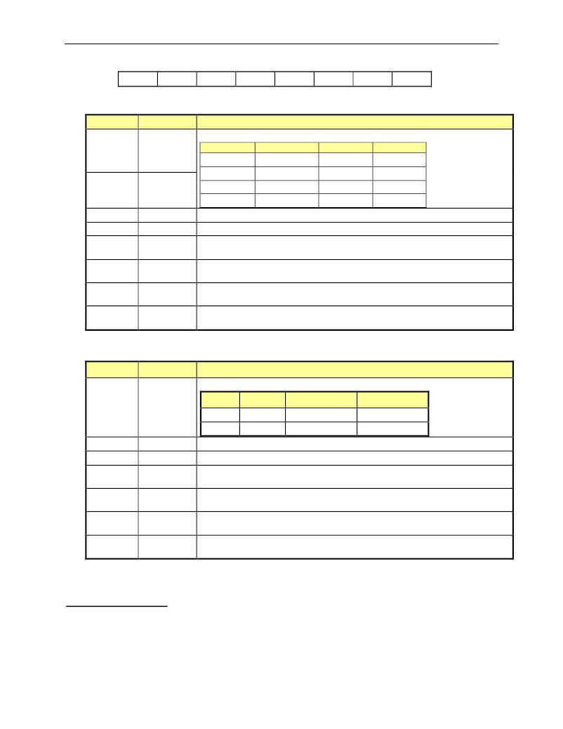
�Table� 16:� The� S1CON� register�
�Bit�
�S0CON.7�
�Symbol�
�SM0�
�Function�
�These two bits� set� the� UART0� mode:�
�Mode�
�0�
�Description�
�N/A�
�SM0�
�0�
�SM1�
�0�
�S0CON.6�
�SM1�
�1�
�2�
�3�
�8-bit� UART�
�9-bit� UART�
�9-bit� UART�
�0�
�1�
�1�
�1�
�0�
�1�
�S0CON.5�
�S0CON.4�
�S0CON.3�
�S0CON.2�
�S0CON.1�
�S0CON.0�
�Bit�
�S1CON.7�
�SM20�
�REN0�
�TB80�
�RB80�
�TI0�
�RI0�
�Symbol�
�SM�
�Enables� the� inter-processor� communication� feature.�
�If� set,� enables� serial� reception.� Cleared� by� software� to� disable� reception.�
�The� 9� th� transmitted� data� bit� in� Modes� 2� and� 3.� Set� or� cleared� by� the� MPU,� depending�
�on� the� function� it� performs� (parity� check,� multiprocessor� communication� etc.)�
�In� modes� 2� and� 3� it� is� the� 9� th� data� bit� received.� In� Mode� 1,� if� SM20� is� 0,� RB80� is� the�
�stop� bit.� In� mode� 0� this� bit� is� not� used.� Must� be� cleared� by� software�
�Transmit� interrupt� flag,� set� by� hardware� after� completion� of� a� serial� transfer.� Must� be�
�cleared� by� software.�
�Receive� interrupt� flag,� set� by� hardware� after� completion� of� a� serial� reception.� Must�
�be� cleared� by� software�
�Table� 17:� The� S0CON� Bit� Functions�
�Function�
�Sets� the� baud� rate� for� UART1�
�SM�
�0�
�1�
�Mode�
�A�
�B�
�Description�
�9-bit� UART�
�8-bit� UART�
�Baud� Rate�
�variable�
�variable�
�The� 9� transmitted� data� bit� in� Mode� A.� Set� or� cleared� by� the� MPU,� depending� on� the�
�S1CON.5�
�S1CON.4�
�S1CON.3�
�S1CON.2�
�S1CON.1�
�S1CON.0�
�SM21�
�REN1�
�TB81�
�RB81�
�TI1�
�RI1�
�Enables� the� inter-processor� communication� feature.�
�If� set,� enables� serial� reception.� Cleared� by� software� to� disable� reception.�
�th�
�function� it� performs� (parity� check,� multiprocessor� communication� etc.)�
�In� Modes� A� and� B,� it� is� the� 9� th� data� bit� received.� In� Mode� B,� if� SM21� is� 0,� RB81� is� the�
�stop� bit.� Must� be� cleared� by� software�
�Transmit� interrupt� flag,� set� by� hardware� after� completion� of� a� serial� transfer.� Must� be�
�cleared� by� software.�
�Receive� interrupt� flag,� set� by� hardware� after� completion� of� a� serial� reception.� Must�
�be� cleared� by� software�
�Table� 18:� The� S1CON� Bit� Functions�
�Timers and Counters�
�The� 80515� has� two� 16-bit� timer/counter� registers:� Timer� 0� and� Timer� 1.� These� registers� can� be� configured� for� counter�
�or� timer� operations.�
�In� timer� mode,� the� register� is� incremented� every� machine� cycle� meaning� that� it� counts� up� after� every� 12� periods� of� the�
�MPU� clock� signal.�
�Rev� 3�
�Page:� 25� of� 107�
�发布紧急采购,3分钟左右您将得到回复。
相关PDF资料
71M6531F-DB
BOARD DEMO 71M6531F
71M6533-DB
BOARD DEMO 71M6533
71M6534H-DB
BOARD DEMO 71M6534H
71M6541F-DB
DEMO BOARD 71M6541F
71M6543F-DB-CT
DEMO BOARD 71M6543F-DB-CT
72-CNV-5
CONVERTER RS-232 TO RS-422 5V
72346-001
72346-1-SCA-II REC
72347-001LF
CONN RECEPT SCA2 20POS VERT PCB
相关代理商/技术参数
71M6521FE-IGT
制造商:Maxim Integrated Products 功能描述:Metering Systems on a Chip - SoC Residential Energy Meter IC
71M6521FE-IGT/F
功能描述:计量片上系统 - SoC Residential Energy Meter IC RoHS:否 制造商:Maxim Integrated 核心:80515 MPU 处理器系列:71M6511 类型:Metering SoC 最大时钟频率:70 Hz 程序存储器大小:64 KB 数据 RAM 大小:7 KB 接口类型:UART 可编程输入/输出端数量:12 片上 ADC: 安装风格:SMD/SMT 封装 / 箱体:LQFP-64 封装:Reel
71M6521FE-IGT/F1
功能描述:计量片上系统 - SoC
RoHS:否 制造商:Maxim Integrated 核心:80515 MPU 处理器系列:71M6511 类型:Metering SoC 最大时钟频率:70 Hz 程序存储器大小:64 KB 数据 RAM 大小:7 KB 接口类型:UART 可编程输入/输出端数量:12 片上 ADC: 安装风格:SMD/SMT 封装 / 箱体:LQFP-64 封装:Reel
71M6521FE-IGTR
制造商:Maxim Integrated Products 功能描述:Metering Systems on a Chip - SoC Residential Energy Meter IC
71M6521FE-IGTR/F
功能描述:计量片上系统 - SoC Residential Energy Meter IC RoHS:否 制造商:Maxim Integrated 核心:80515 MPU 处理器系列:71M6511 类型:Metering SoC 最大时钟频率:70 Hz 程序存储器大小:64 KB 数据 RAM 大小:7 KB 接口类型:UART 可编程输入/输出端数量:12 片上 ADC: 安装风格:SMD/SMT 封装 / 箱体:LQFP-64 封装:Reel
71M6521FE-IGTR/F1
功能描述:计量片上系统 - SoC
RoHS:否 制造商:Maxim Integrated 核心:80515 MPU 处理器系列:71M6511 类型:Metering SoC 最大时钟频率:70 Hz 程序存储器大小:64 KB 数据 RAM 大小:7 KB 接口类型:UART 可编程输入/输出端数量:12 片上 ADC: 安装风格:SMD/SMT 封装 / 箱体:LQFP-64 封装:Reel
71M6521FE-IM
制造商:Maxim Integrated Products 功能描述:Metering Systems on a Chip - SoC Residential Energy Meter IC
71M6521FE-IM/F
功能描述:计量片上系统 - SoC Residential Energy Meter IC RoHS:否 制造商:Maxim Integrated 核心:80515 MPU 处理器系列:71M6511 类型:Metering SoC 最大时钟频率:70 Hz 程序存储器大小:64 KB 数据 RAM 大小:7 KB 接口类型:UART 可编程输入/输出端数量:12 片上 ADC: 安装风格:SMD/SMT 封装 / 箱体:LQFP-64 封装:Reel